State machines model discrete behavior through finite state-transition systems. They can be used to model the behavior of individual entities at any level of granularity like individual class instances, subsystems, etc.
State machines model discrete behavior through finite state-transition systems. They can be used to model the behavior of individual entities at any level of granularity like individual class instances, subsystems, etc.
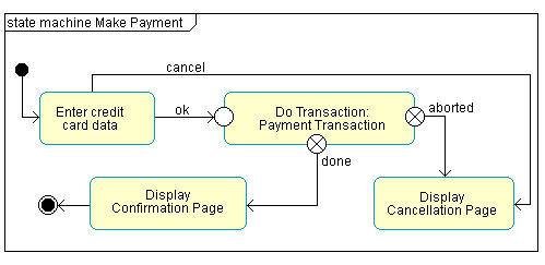
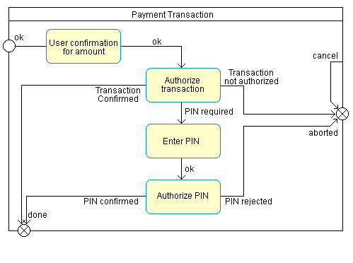
A state machine diagram is typically used to model the discrete stages of an object's lifetime. They show the sequences of state that an object goes through, the events that cause a transition from one state to another state, and the actions that result from the state change.
Each state represents a named condition during the life of an object in which it satisfies some condition or waits for some event. A state machine diagram typically contains one start and multiple end states. Transitions connect the various states on the diagram.
State machines are used to model the dynamic behavior of a model element, and more specifically, the event-driven aspects of the system's behavior. State machines are specifically used to define state-dependent behavior, or behavior that varies depending on which state the model element is in. Model elements, whose behavior does not vary with the state, do not require state machines to describe their behavior. These elements are typically passive classes whose primary responsibility is to manage data.