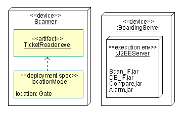
Deployment models describe the assignment of executable artifacts to the underlying platform.
Deployment diagrams allow you to visualize a system's physical layout, revealing which artifacts are deployed on what pieces of hardware. The essential elements of a deployment diagram are nodes and their connectors.
The deployment diagram also maps processes on to these processing elements, allowing the distribution of behavior across nodes to be represented.
A node is a run-time physical object that represents a computational resource, generally having at least memory and often processing capability as well.
Nodes come in two forms: a device is hardware and an execution environment is software that itself hosts or contains other software. The nodes contain artifacts, which are the physical manifestations of deployed software.
Communication paths, or connectors, between nodes indicate how things communicate. These connectors represent communication mechanisms and can be described by physical mediums (for example, Ethernet, fiber optic cable) or software protocol (for example, TCP/IP, RS-232). A stereotype may be used to specify the type of connector.
