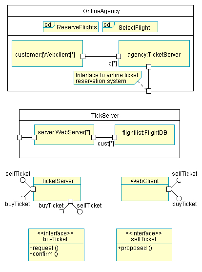
Composite structures define the parts of a system and the communication relationships between them. This provides the ability to hierarchically decompose a classifier and visually depict the internal structure which is useful for describing runtime architectures.
The composite structure diagram is similar to a class diagram except for the internal structure which is composed of parts and connectors. Parts are not instance specifications, so the name is not underlined, but represent the roles classifiers play to support the structural features required of the enclosing classifier.
You can access features of the structure using interaction points, or ports. Ports can be added to the external structure which allow you to group the required and provided interfaces into logical interactions that a classifier has with the outside world.
To show a part implementing an interface, or needing an interface, draw a delegation connector between the part and the interface. You can also use [assembly] connectors between parts with either a simple line or with the ball-and-socket notation.
Unlike package diagrams which show compile-time groupings, composite structures show runtime groupings so they are a natural fit for visualizing components; hence, much of this notation is also used in component diagrams.
